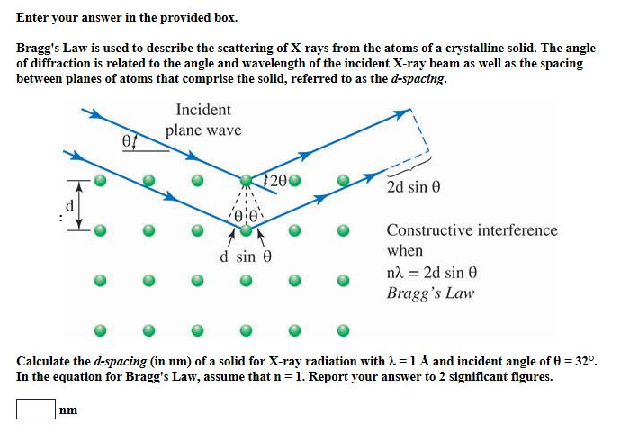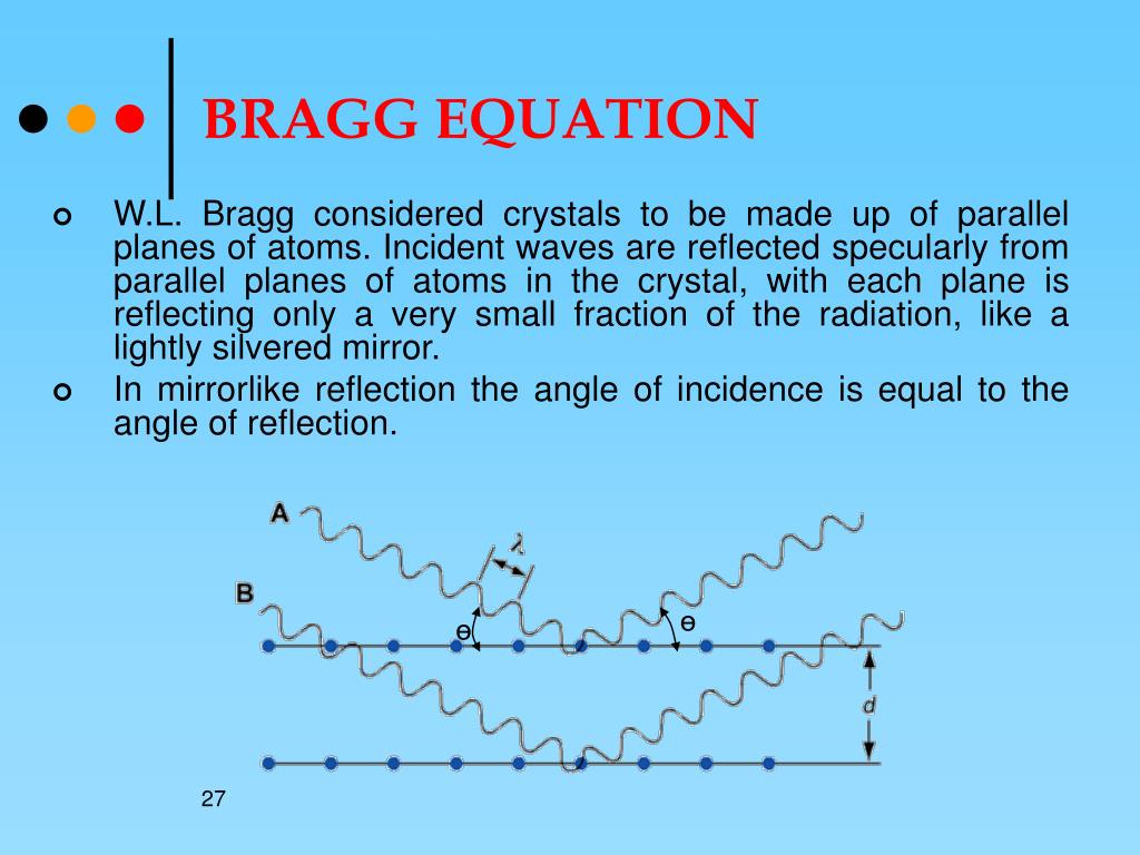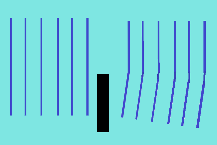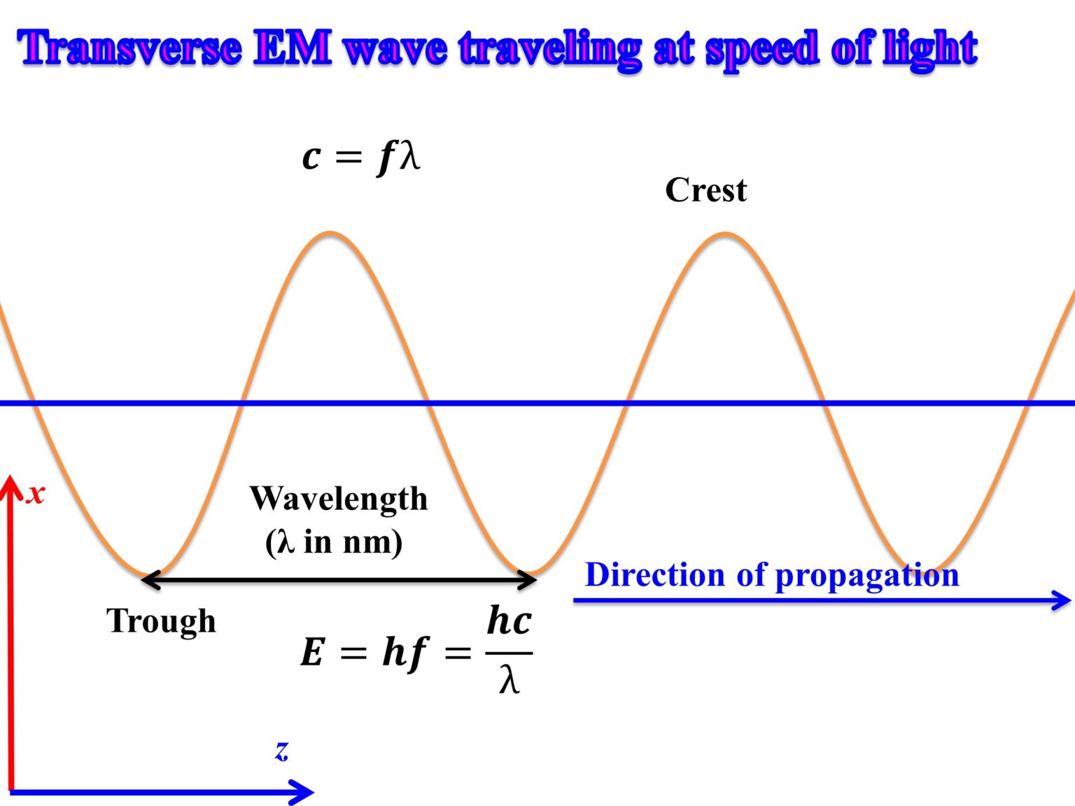
For example, if the incident angle α = 30° and the groove density N = 2400 grooves/mm, applying the equation to first-order light (i.e., m = +1) with a wavelength λ of 700nm gives sin ß = 1.18, then diffracted light cannot be obtained in this case. One point requiring consideration is that, depending on the groove density N, it may not be possible to obtain diffracted light. The diffraction angle ß also varies with the groove density N and the incident angle α. This is why gratings can be used to separate white light into its constituent wavelengths. It can also be seen that for m ≠ 0 the diffraction angle ß is different for each wavelength. It can be seen from this relationship that all components of light corresponding to m = 0 (zero-order light) are radiated in a straight line and so it is not possible to separate the wavelengths with this order. N : Number of slits per mm ( the groove density, equal to the reciprocal of the grating period) 1-2 The Principle of Reflection GratingsĪs shown in Fig.1-1 and Fig.1-2, α is the angle between the incident light and the normal to the grating (the incident angle) and ß is the angle between the diffracted light and the normal to the grating (the diffraction angle), then, they satisfy the following relationship:Īs shown in Fig.1-1, in case of transmission gratingĪs shown in Fig.1.2 in case of a reflection grating,ĭ : Spacing between the slits (the grating period) The light from all the slits is reinforced in the same way to produce "diffracted light."įig. 1, light is reinforced when the optical path difference is a multiple of the wavelength. In short, for parallel beams that enter neighboring slits as shown in Fig. Picking out diffracted (reinforced) light makes it possible to select the required light component. When white light enters the grating, the light components are diffracted at angles that are determined by the respective wavelengths (diffraction).

The simplest type of grating is one with a large number of evenly spaced parallel slits. Our Technology for Manufacturing GratingsĪ diffraction grating is an optical element that divides (disperses) light composed of lots of different wavelengths(e.g., white light) into light components by wavelength. In this process, most of the energy is released as heat and X-ray only account for approximately 1% of total energy. Electrons travel from cathode to anode through a high acceleration voltage, typically 30~150kV. The cathode part of X-ray tube generated electrons under electric current. Synchrotron radiation is a brighter source and as a result can increase the resolution. X-ray tube equipped with filter is commonly used in laboratory diffractometer. Possible X-ray sources are X-ray tube, Synchrotron radiation and cyclotron radiation.

The other common rules for reflection to be observed are listed as follows: Table 2.3.1: Systematic absence due to lattice type.


Structure factor is important in the structure determination step because it helps understand the Miller indices and intensities of diffraction peaks. For the other situation, F=0 and thus diffraction intensity will also be zero. When h, k, l are all odd or all even, F=4f.


 0 kommentar(er)
